Security Researcher, Cat Lover and Escape Room Aficionado!
Security Researcher, Cat Lover and Escape Room Aficionado!
04 May 2026
This project involved designing a PWM-controlled driver circuit for a high-powered electromagnet coil, with the goal of propelling a steel ball to a specific target height along a vertical rail — and doing so without overheating the coil.
The task sits at the intersection of power electronics, magnetic force calibration, and thermal management: too little current and the ball doesn’t reach the target; too much current sustained for too long and the coil resistance climbs, the insulation degrades, and the winding fails.
The driver circuit was designed in PCB layout software, fabricated in-house using chemical etching, and tested on a purpose-built bench rig.
The magnetic force an electromagnet exerts on a steel ball falls off sharply with distance — roughly proportional to 1/r² at the near-field distances relevant here. This means:
The coil therefore cannot simply be driven at full power — the current must be calibrated so the ball reaches the target height and no higher.
A high-powered coil wound from many turns of copper wire has measurable DC resistance. When current flows, power is dissipated as heat:
P = I² × R
For sustained high-current operation this heat builds up in the winding. Copper resistivity increases with temperature, which in turn increases resistive losses further — a positive feedback loop. Beyond a threshold, the enamel insulation on the wire degrades, causing inter-winding shorts and coil failure.
The design therefore had to operate within a thermal budget: either by limiting pulse duration, enforcing a minimum off-time between pulses (allowing the coil to cool), or by calibrating the duty cycle such that steady-state temperature stays within safe limits.
The driver uses a two-stage switching circuit. A logic-level PWM signal from a microcontroller cannot directly drive a power MOSFET gate with sufficient speed, so an intermediate BJT stage is used:
Stage 1 — 2N3904 NPN BJT (gate driver)
Stage 2 — FED140P P-Channel MOSFET (main power switch)
| Component | Part | Function |
|---|---|---|
| Q1 | 2N3904 NPN BJT | PWM gate driver / level shifter |
| Q2 | FED140P P-ch MOSFET | High-side coil current switch |
| R1 | 1 kΩ | BJT base current limiting resistor |
| R2 | 4.7 kΩ | BJT base pull-down (ensures off-state when PWM floats) |
| R3 | 2 kΩ | MOSFET gate resistor (controls switching speed, limits gate ringing) |
| R4 | 22 kΩ | MOSFET gate pull-up to V_supply (ensures MOSFET is off if gate driver loses drive) |
| C1 | Decoupling capacitor | Suppresses supply voltage spikes during switching transients |
| D1 | Flyback diode | Clamps inductive kick when MOSFET turns off |
| JP1–JP6 | 2-pin headers | PWM input, supply, and coil connections |
When the MOSFET switches off, the energy stored in the coil’s magnetic field (E = ½LI²) must discharge. Without a flyback diode, the resulting back-EMF spike can reach hundreds of volts and destroy the MOSFET. A flyback (freewheeling) diode placed in anti-parallel across the coil provides a low-impedance recirculation path, clamping the spike to one diode drop above the supply rail.
The 2 kΩ gate resistor (R3) controls the MOSFET’s switching speed. A faster switch-on reduces switching losses, but creates steeper di/dt edges that induce ringing on the supply lines. The gate resistor value was chosen as a compromise — fast enough to minimise thermal dissipation in the MOSFET during transition, slow enough to keep supply noise manageable.
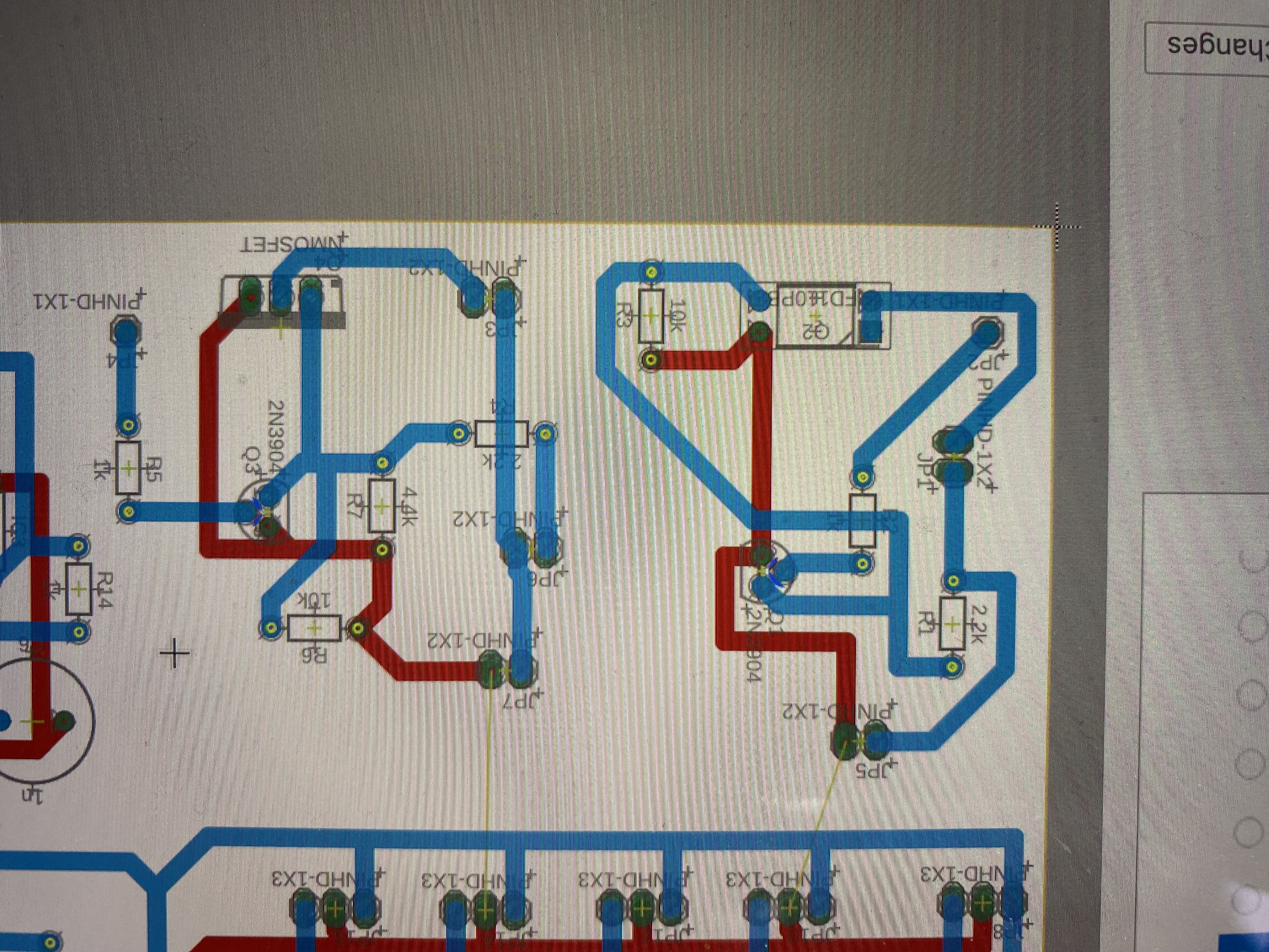
The PCB layout was done in two copper layers:
Power traces were sized using the IPC-2221 current-capacity guidelines for the expected peak coil current, ensuring the copper width could handle the thermal load at the trace level without resistive drop adding to the overall driver inefficiency.
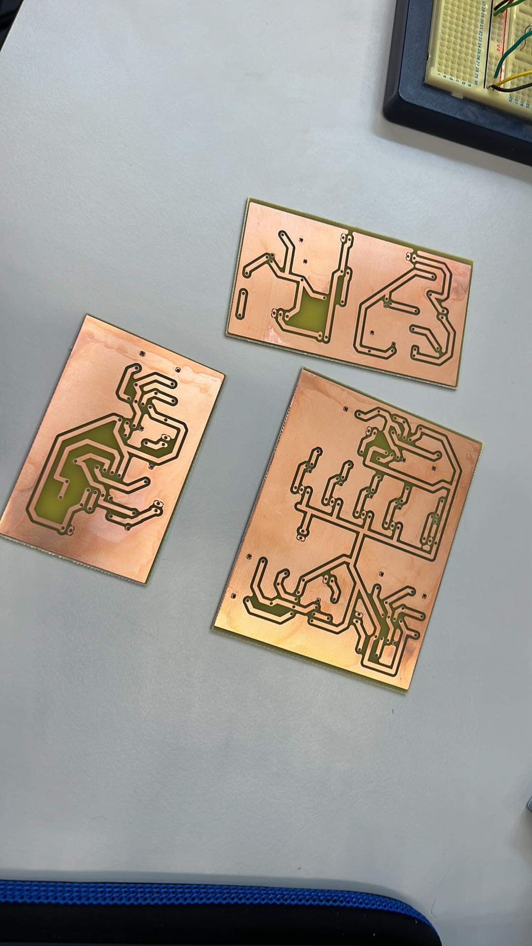
Three board variants were etched in a single session using the toner-transfer / ferric chloride process. The different sizes correspond to iterative layout revisions: early versions verified the gate drive behaviour with a small test load; the final board was sized for the full coil current.
To stay within the coil’s thermal limits, the following strategies were implemented:
1. Pulse-and-cool operation Rather than applying DC current, the coil was driven with a controlled pulse of fixed duration. After each firing, a minimum off-time was enforced to allow the winding to dissipate heat into the surrounding air before the next pulse.
2. PWM duty cycle calibration The duty cycle was tuned empirically: starting low and incrementing until the ball consistently reached the target height, then locking that setting. Running the coil at the minimum duty cycle necessary (rather than full power) directly reduces I²R losses.
3. Coil resistance monitoring Coil resistance increases measurably with temperature (copper has a temperature coefficient of ~0.004 /°C). By monitoring supply voltage and current draw, resistance could be inferred and used as a proxy for winding temperature — if resistance climbed beyond a threshold, firing was inhibited until it fell back.
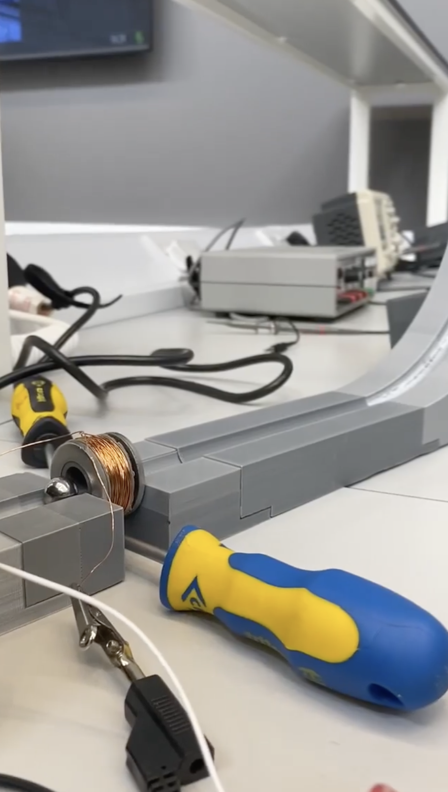
The lab setup shows the electromagnet coil mounted in a vertical rail fixture (aluminium extrusion channel) with the steel ball constrained to move along the rail axis. A bench power supply provided the coil voltage, and an oscilloscope monitored the drain voltage of the MOSFET to confirm clean switching and verify the flyback clamp was operating correctly.
Ball height was measured visually against a calibrated scale on the rail, with pulse parameters adjusted between shots until the target height was reliably achieved.
The circuit successfully controlled ball height to the target specification across repeated firings, with the thermal management strategy keeping coil temperature within safe operating range. The combination of BJT gate drive and P-channel MOSFET switching provided reliable, repeatable performance, with no component failures across the test duration.