Security Researcher, Cat Lover and Escape Room Aficionado!
Security Researcher, Cat Lover and Escape Room Aficionado!
04 May 2026
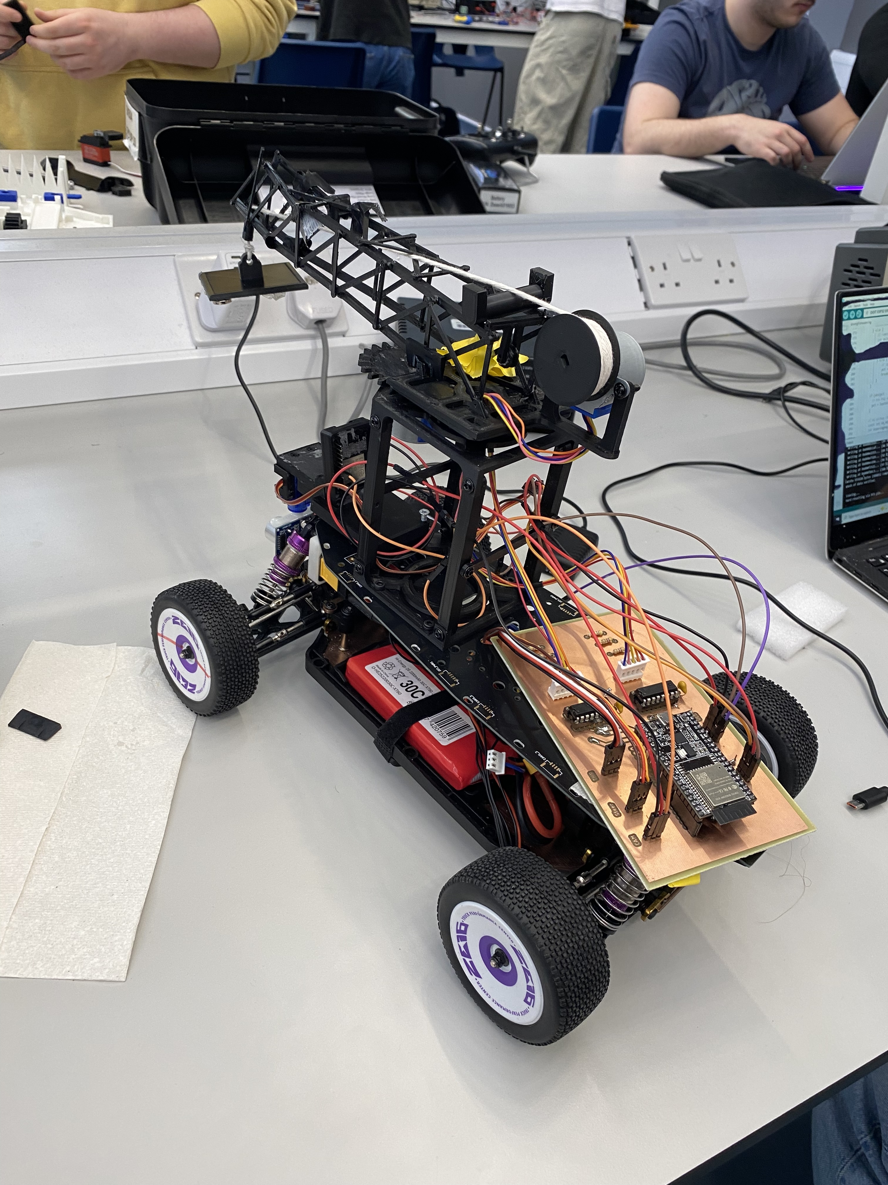
This project was built for a robotics competition requiring an autonomous vehicle to navigate to objects and retrieve them using a motorised crane. The car had to operate fully autonomously — driving, positioning, extending the crane arm, and picking up targets without human input.
The custom control electronics were designed from scratch in Autodesk EAGLE, etched in-house, assembled, and integrated onto the RC car chassis.
The competition task demanded simultaneous control of multiple independent systems:
All of this had to run from a single embedded controller, coordinating motor drive outputs, sensor reads, and servo commands in real time.
| Subsystem | Implementation |
|---|---|
| Main controller | ESP32 (dual-core, 240 MHz, Wi-Fi + Bluetooth) |
| Drive motors | Two DC motors via dual H-bridge motor driver ICs |
| Crane actuation | Servo motor(s) controlling arm extension and gripper |
| Power supply | LiPo battery pack with regulated 3.3 V / 5 V rails |
| Comms | Wi-Fi for telemetry and remote monitoring during testing |
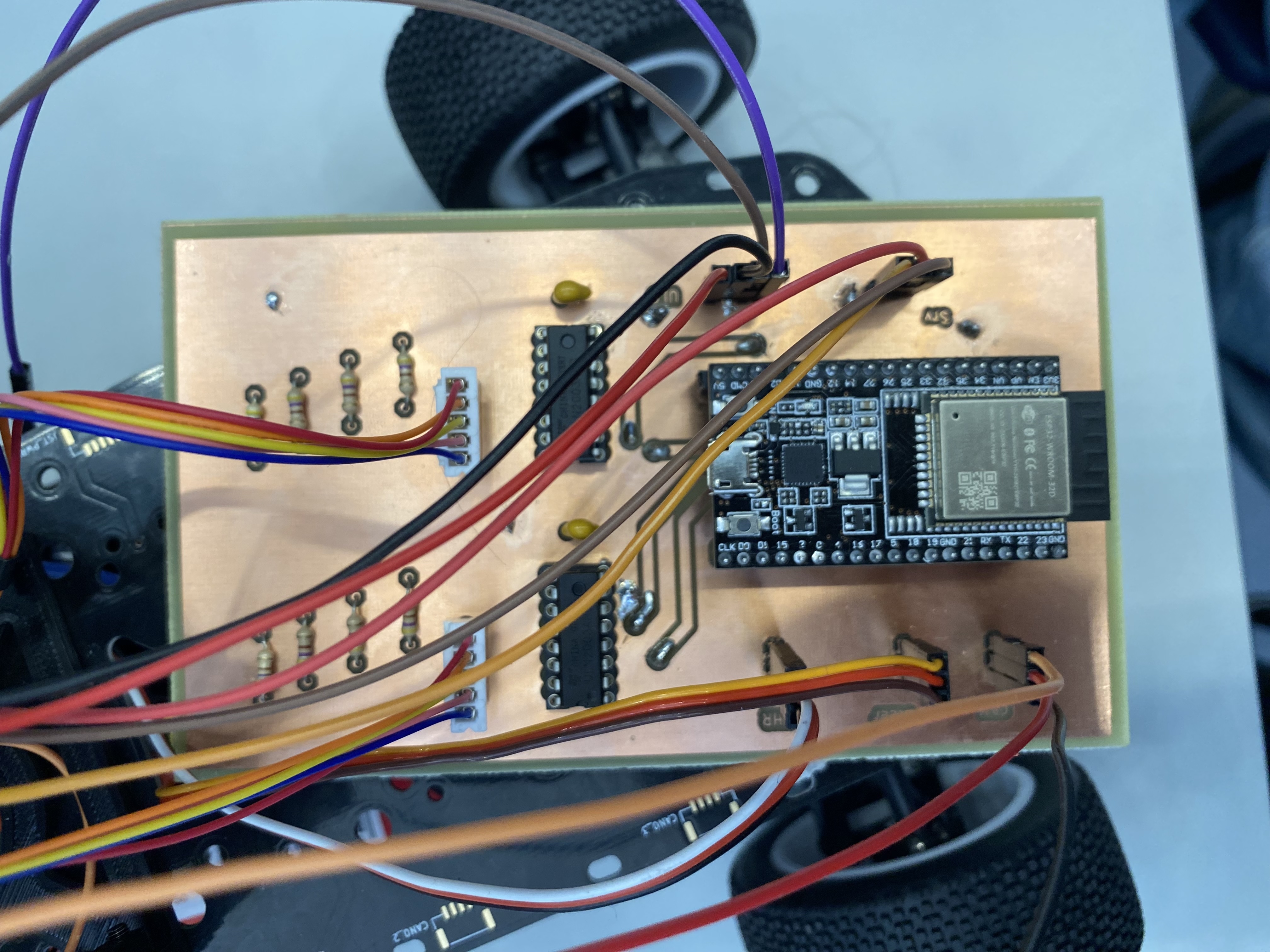
The control board was laid out in Autodesk EAGLE and fabricated in-house on single-sided copper-clad FR4. EAGLE’s schematic-to-layout workflow was used throughout: the schematic was fully captured with net connections before switching to the PCB editor, ensuring the layout was electrically validated against the design before committing to fabrication.
The ESP32 sits at the centre of the design, providing:
Two DIP-package dual H-bridge motor driver ICs handle the four motor outputs:
DIP packages were deliberately chosen for the competition build — they are hand-solderable, replaceable in the field, and survive the rough handling of a competition environment better than fine-pitch SMD parts.
The through-hole resistor array visible on the board provides:
The colour-coded wire harness connects the board to the full vehicle:
| Colour | Function |
|---|---|
| Red / Black | LiPo power and ground |
| Yellow / Orange | Drive motor A and B |
| Purple | Crane lift motor |
| Brown | Servo signal |
| Red / Yellow striped | Sensor power and signal |
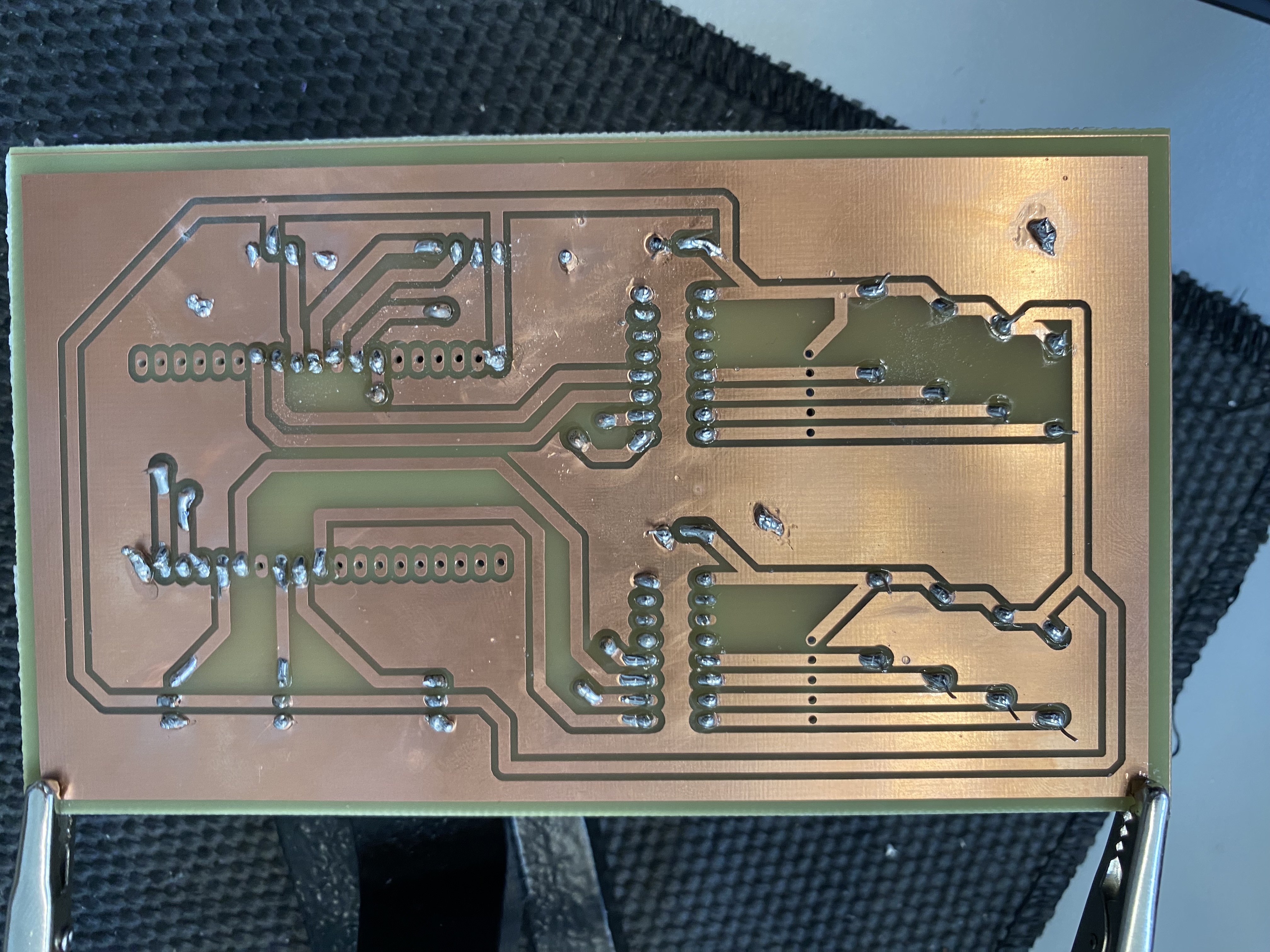
The board was fabricated using the toner-transfer chemical etching process:
The reverse side of the board shows the characteristic hand-etched single-layer trace layout — the two large DIP IC footprints dominate the left half of the board, with the ESP32 header spanning the right and the passive component field filling the centre.
The competition run sequence implemented in firmware:
Wi-Fi telemetry logged each stage transition in real time, allowing post-run analysis of where navigation errors occurred.
The assembled robot successfully demonstrated autonomous crane operation in competition conditions. The custom PCB provided reliable motor drive and servo control throughout, with the ESP32’s dual-core architecture allowing navigation logic to run on one core while motor PWM outputs were managed on the other — avoiding the timing conflicts that arise when both run in the same execution loop.